Logic circuits always specify the voltage levels required for correct operation.
Binary digital circuits of course have 1’s and 0’s, which are typically defined as high and low voltage respectively.
There are several different standards for logic levels and it is important to know the implications of mixing logic families with different standards.
Logic Level Parameters
Any logic gate will have inputs and outputs, and both of them have defined levels.
Input Parameters
To correctly interpret a 0, the input voltage VI must be below a threshold value, called VIL (voltage input low).
Similarly, to read a 1 the voltage must be above a threshold value, call VIH (voltage input high).
0 = VI < VIL 1 = VI > VIH
Typically VIL and VIH depend on the supply voltage VCC to the part in addition to the inherent technology.
Any input in-between VIL and VIH is not defined and is likely to result in unstable outputs, oscillations or extraneous power consumption.
Output Parameters
Ideally the output voltage of a logic gate is 0 V for a 0, and VCC for a 1.
In general, the output voltage follows a curve based on the input and therefore
In addition there is a non-zero output resistance and therefore the output voltage also depends on the load impedance.
A datasheet will provide guaranteed output values for some specified input/load condition.
So, for a 0 the output VO is guaranteed to be below VOL (voltage output low), and for a 1 the output is guaranteed to be above VOH (voltage output high).
0 = VO < VOL 1 = VO > VOH
The output will never be in-between VOL and VOH unless the input is undefined.
Noise Margin
Digital circuits are intentionally designed to ignore a fairly large amount of noise and this is done by separating the input and output parameters.
This is called noise margin, and is defined below:
NMH = VOH – VIH
NML = VOL – VIL
If a gate is guaranteed to output less than 0.2 V, and the following gate input is guaranteed to read the value correctly if its below 0.5 V, then there can be up to 0.5 – 0.2 = 0.3 V of noise on top of the output without causing an error.
Real World Examples
There are many different types of logic but the most common are CMOS and TTL.
CMOS
CMOS logic uses FET’s which have very high input impedance (capacitive) and are capable of strongly driving the output.
They tend to be symmetrical and have very low power consumption.
FET’s in general are lower performance than BJT’s so CMOS is mainly used due to density requirements.
With modern electronics these disadvantages are completely invisible behind decades of process improvements, and CMOS parts are capable of incredible performance.
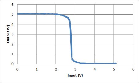
Inverter
The CD family of parts has symmetric VIL and VIH, and can output all the way to 0V or 5V for a CMOS load.
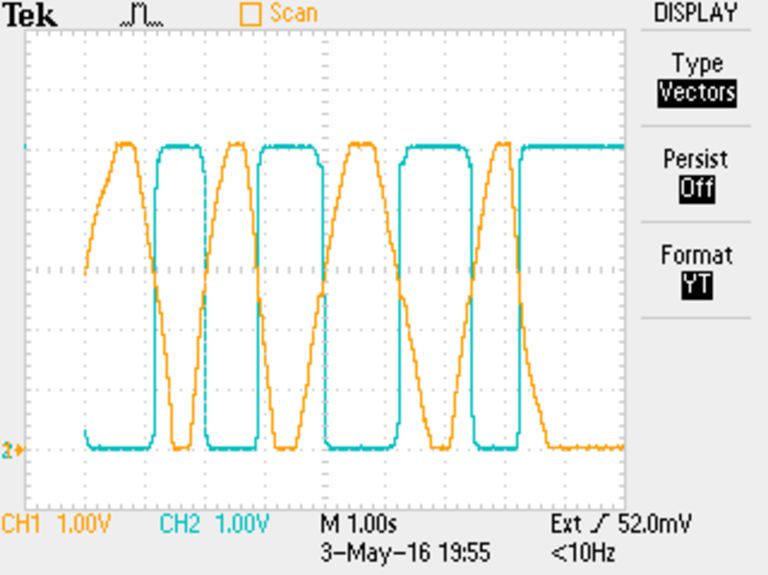
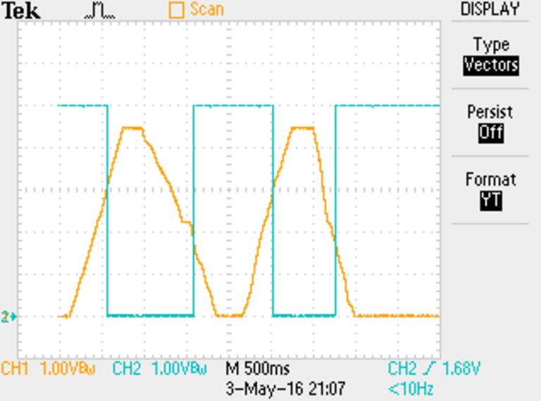
Schmitt Trigger
A Schmitt trigger is a special kind of logic gate that has hysteresis. That is, the input voltage threshold is different depending on the current output.
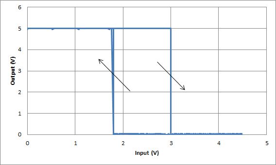
The device tested here shows 0.6 V of hysteresis, centered on 2.4 V.
When the input is heading high, the threshold is 3 V, and while heading low, the threshold is 1.8 V.
This allows a Schmitt trigger to reject even more noise than a standard logic gate. Another side effect is that the gain is extremely high such that the edges are always sharp regardless of how slow the input is.
TTL
Low-power Schottky
Advanced Schottky with higher speed
boop