A voltage regulator is a device or circuit that maintains a constant output voltage. It’s typical job is to convert from one voltage to another. Other common usages are to stabilize a variable supply, such as a battery which discharges over time, or to provide a noise-free supply to a sensitive subcircuit.
Voltage regulators are a good study of an electronic system because they have many identifiable and relatively simple functional blocks.
Contents
Fundamental Types
Ignoring implementation details entirely, there are several types of regulator.
Series or Shunt
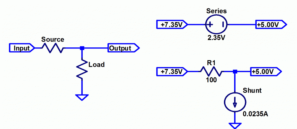
Thinking of a resistor voltage divider, there are two ways to control an output voltage; vary the series/source resistor, or the shunt/load resistor.
A series voltage regulator uses a device which controls the voltage drop across itself to maintain a constant output.
A shunt regulator controls the current through itself and its interaction with the source resistance varies voltage. The current is adjusted for constant output voltage
The diagram below shows the options.

Shunt regulators are speciality devices, with series regulators being the vast majority of applications. Shunt regulators are mainly used as low power precision voltage references or as energy absorbing voltage limiters in motor drivers.
This is because a shunt regulator requires either a high source resistance to work with or it needs to sink a lot of current. A typical power system has very low source resistance and therefore the shunt regulator often needs more current than the load itself, wasting huge amounts of power.
Linear or Switching
The simplest kind of regulator is linear, where a transistor or other power device is used as a variable resistor. These regulators are only as efficient as Ohm’s law dictates for a given input, output and current. Typical applications are between 30% and 70% efficient.
Switching regulators use transistors as switches instead of as resistors. By combining these with energy storage devices like capacitors and inductors, voltage can be controlled without wasting so much power. Typical efficiencies are 70% to 90%.
A description of how switching regulators work is a left to another post.
Step up or down, inverting or non-inverting
Linear regulators can only reduce or step-down voltage, because they are in essence a resistor.
Switching regulators can step up or down as well as invert the polarity.
Isolated or not
Galvanic isolation refers to breaking the DC connection between the input and output. These typically use transformers and therefore only switching regulators can provide isolation.
Isolation is required for safety in high voltage supplies and is also used for implementing grounding schemes for EMI control.
Functional Blocks
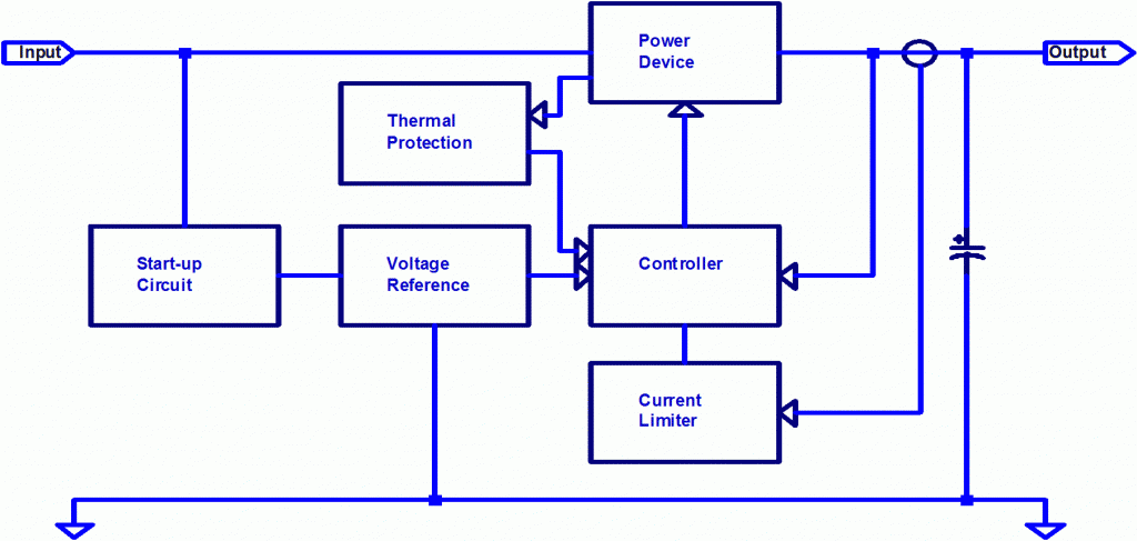
An example block diagram is shown below for a series regulator with some key functional blocks. There is more than one architecture possible and this is only meant as an example.
This diagram is representative of common regulators such as the LM78xx family.

Power Devices
Each voltage regulator will use one or more devices to control the power current. These are the devices that dissipate the majority of the energy lost in the regulator.
For a linear regulator, these are typically either BJT or MOS transistors of p or n type. They are operated in their linear region, hence the name, which simply means that they are used as a resistor.
Control Loop
Most regulators use an active feedback circuit to monitor the output and control the power devices to regulate their output voltage.
In the simplest regulators the control loop is inherent to the devices, relying on diode junction characteristics to maintain a steady voltage over a large range of output current.
Reference
Maintaining a precise output voltage requires a precise voltage reference. The control circuit compares the output to the reference to set the voltage. Any error in the reference directly shows up as an output error. Typical regulators are 2% to 5% accurate.
Current Limiter
Most voltage regulators have a current limiter, which makes the regulator maintain a safe constant current by reducing the output voltage.
This subcircuit needs a way to measure current and a way to override the voltage control loop.
Thermal Protection
As a voltage regulator can dissipate significant power it is common to have built-in thermal protection.
By sensing the temperature of the power devices, the circuit can either shutdown the regulator entirely or reduce the current limit to maintain a safe temperature.
Start-up Circuit
To avoid large in-rush currents it is important to control the ramp-up time of voltages. This is called a soft-start, and is typically accomplished by slowly ramping up the reference voltage.
Some regulators, especially isolated regulators, require a complex start-up circuit to generate transistor control voltages and begin switching.
Filtering or Energy Storage
Transistors inevitably have some delay in how quickly they can adjust and maintain their output, which gives voltage regulators a finite response time. To provide energy quickly, large capacitors are typically included at the output. Capacitors can also maintain output with temporary loss of input power, which is known as hold-up time.
As mentioned previously, switching regulators rely on energy storage elements for their basic operation, where sometimes they are referred to as filters.